


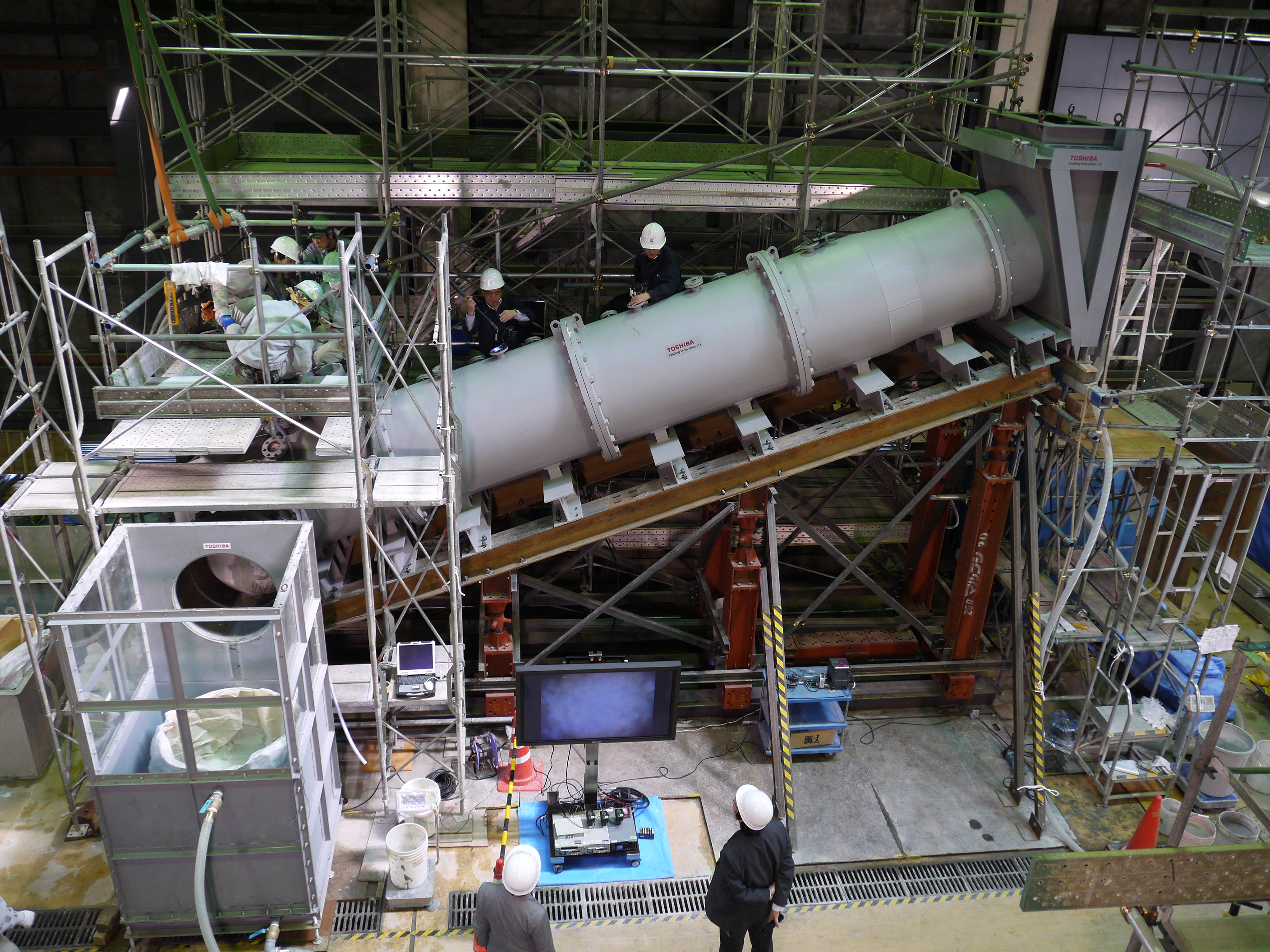
Preliminary Test for “Water Stoppage Method” by Grouting into the Vent Pipe
(“Water stop material” used after conducting a combined test of “Water stop material” and “Support material”) [Toshiba]
(Apr. 17, 2014)
*Scale of test body: one-half of actual unit
On Apr. 17, 2014 Toshiba, a member of IRID, conducted the test for stopping (reducing) water flowing inside the vent pipe by using a half-size model. In this test, we obtained favorable results and the scene of this testing was telecast on Japanese national television. The details of this test are as follows.
The fuel debris retrieval project is based on “Submersion method” (Reference: “Submersion Method CG” https://irid.or.jp/en/video/). This method is expected to have shielding effect on workers against exposure by submerging fuel debris fully, and also be able to prevent dust dispersion during processing of collected debris.
The Submersion method is to be performed while filling PCV and RPV with water, but at present, the PCV and RPV have some leakage points. Therefore, the suppression chamber (S/C) is required to be inspected and the leakage points should be identified and repaired before executing this method.
However, in case of a situation where inspection and repair of the S/C cannot be performed for some reasons, it is necessary to have in place countermeasures against leakage for the lower section of the PCV (S/C). Therefore, a workaround has been put in place, where the S/C is isolated from the PCV even if leaking point of the S/C cannot be detected and repaired. The test conducted this time was to confirm its feasibility from this stage.
Specifically, the water stoppage method of the vent pipe is managed by pouring underwater disjunction material into the bottom head of eight vent pipes to close the water flow path provisionally, and then gradually placing plastic grout upstream of the vent pipe. By doing so, the S/C can be isolated from the PCV boundary.
As one of the concerns on this verification, there is a problem that conduit pipes and its supporting steel materials which will be an interference are placed inside the vent pipe, and these may cause gaps (that form water flow path) after an inflatable bag has been placed. Therefore, some devices were expected to be required for successful water stoppage. In this test, however, plastic grout was piled up well and large amount of leakage could be reduced as planned.
Water stop material is required to have quickly harden (not get flown with running water) and at the same time be fluid enough to be filled tightly into any gaps. It also needs to retain its water stopping properties under the severe conditions that are expected on the actual site. Therefore further testing and data collection for blending of material in order to meet the actual construction conditions and grouting method shall continuously be conducted for further improvement of construction techniques for grouting.

Preliminary Grouting Test
- [Photos] Click image to enlarge.
- [Videos] Click “Download video” to download MP4 file.
[Photos]
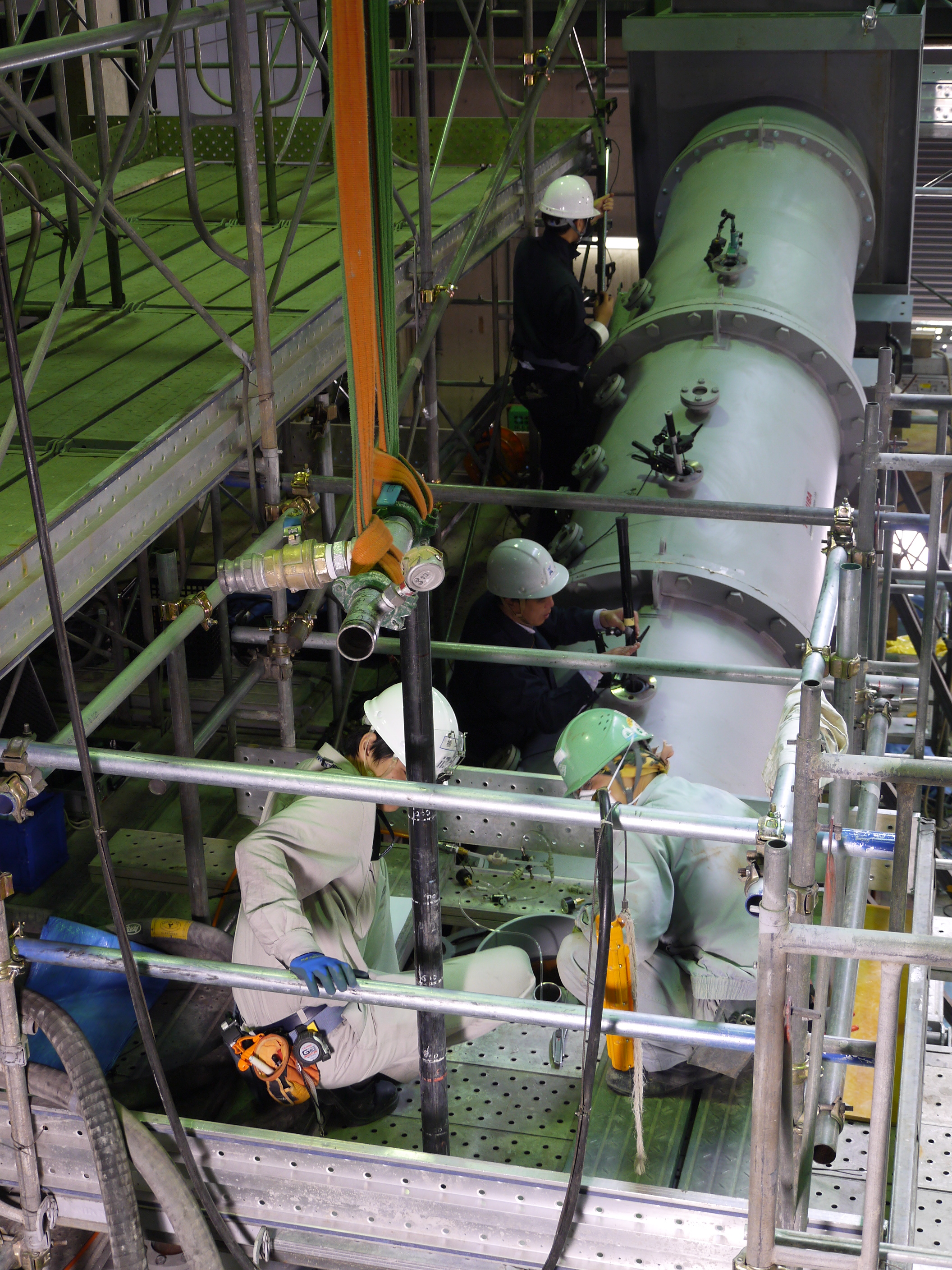
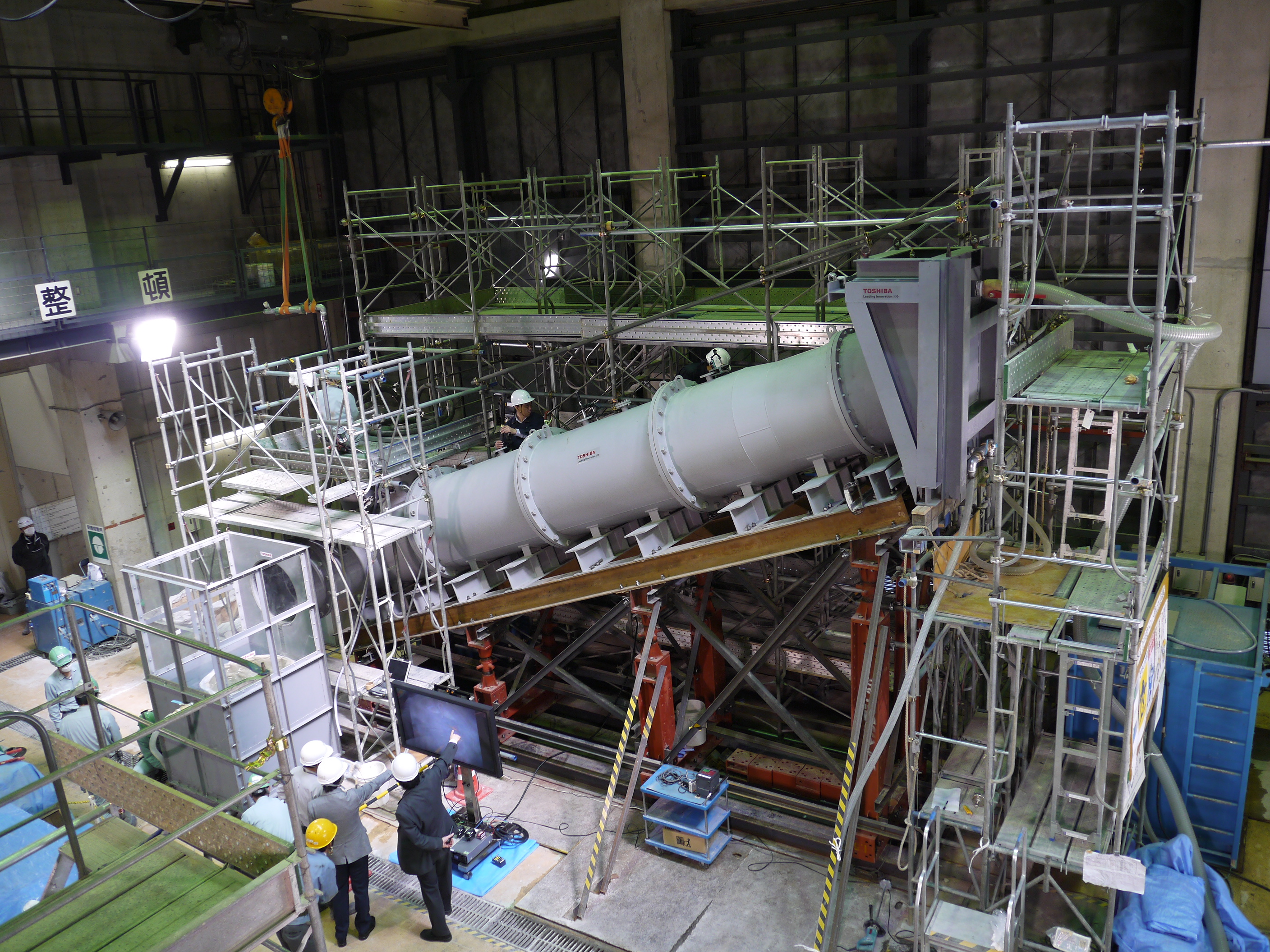
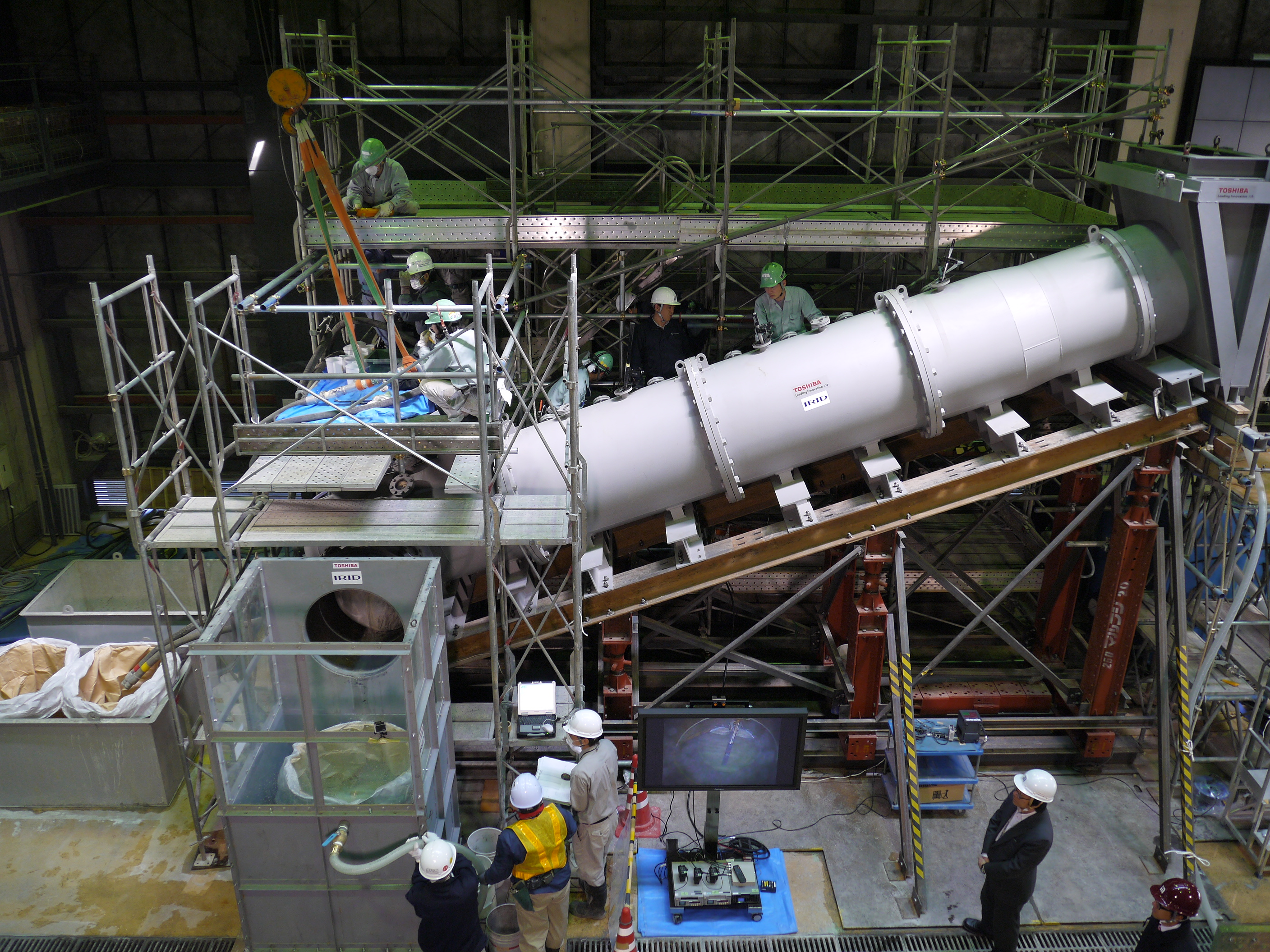
Complete view of testing device for water stoppage method by grouting inside the vent pipe_No.1

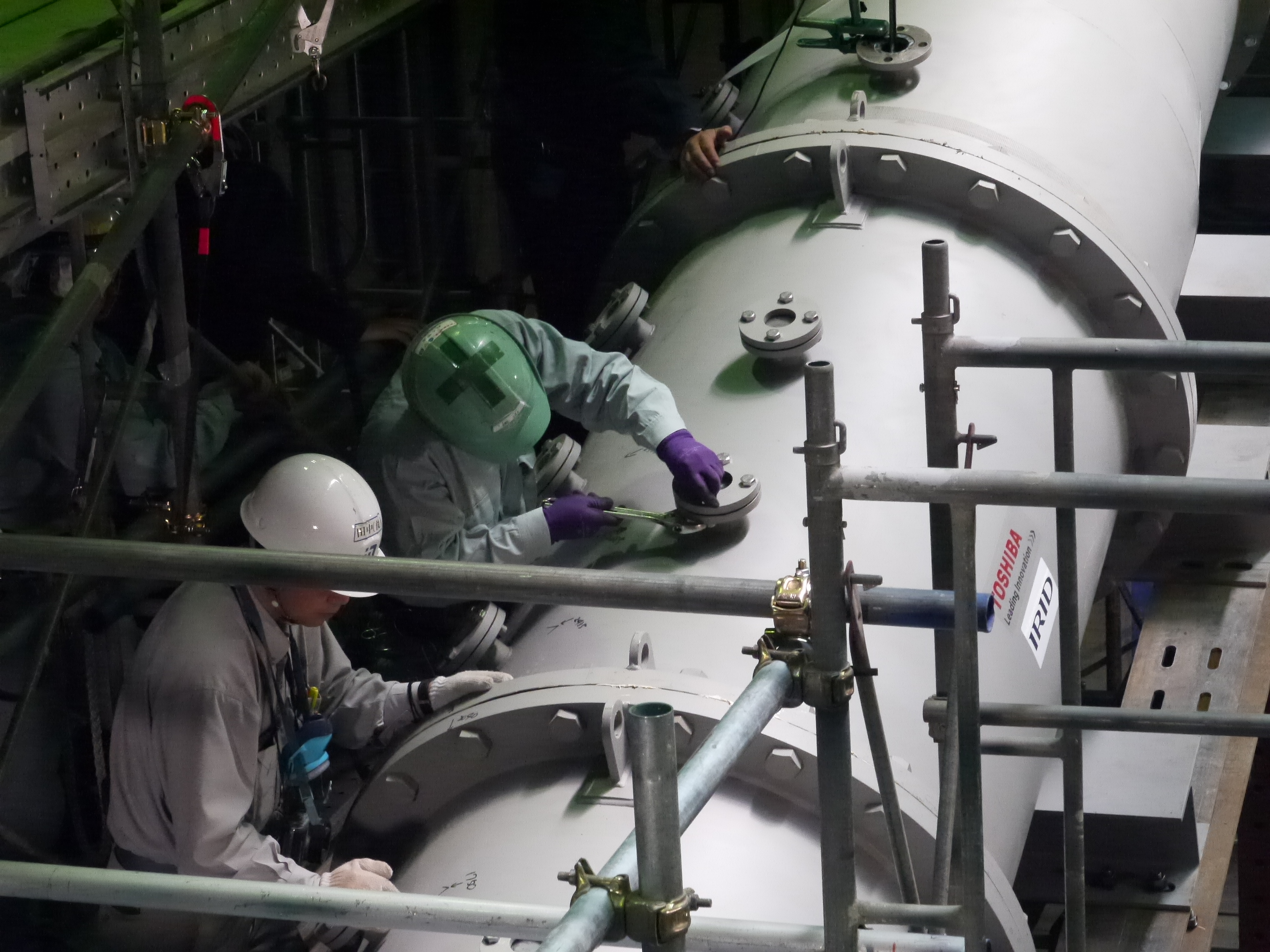
Installation of piping to the testing device for grouting _No.1
Installation of piping to the testing device for grouting _No.2

Complete view of testing device for water stoppage method by grouting inside the vent pipe_No.2
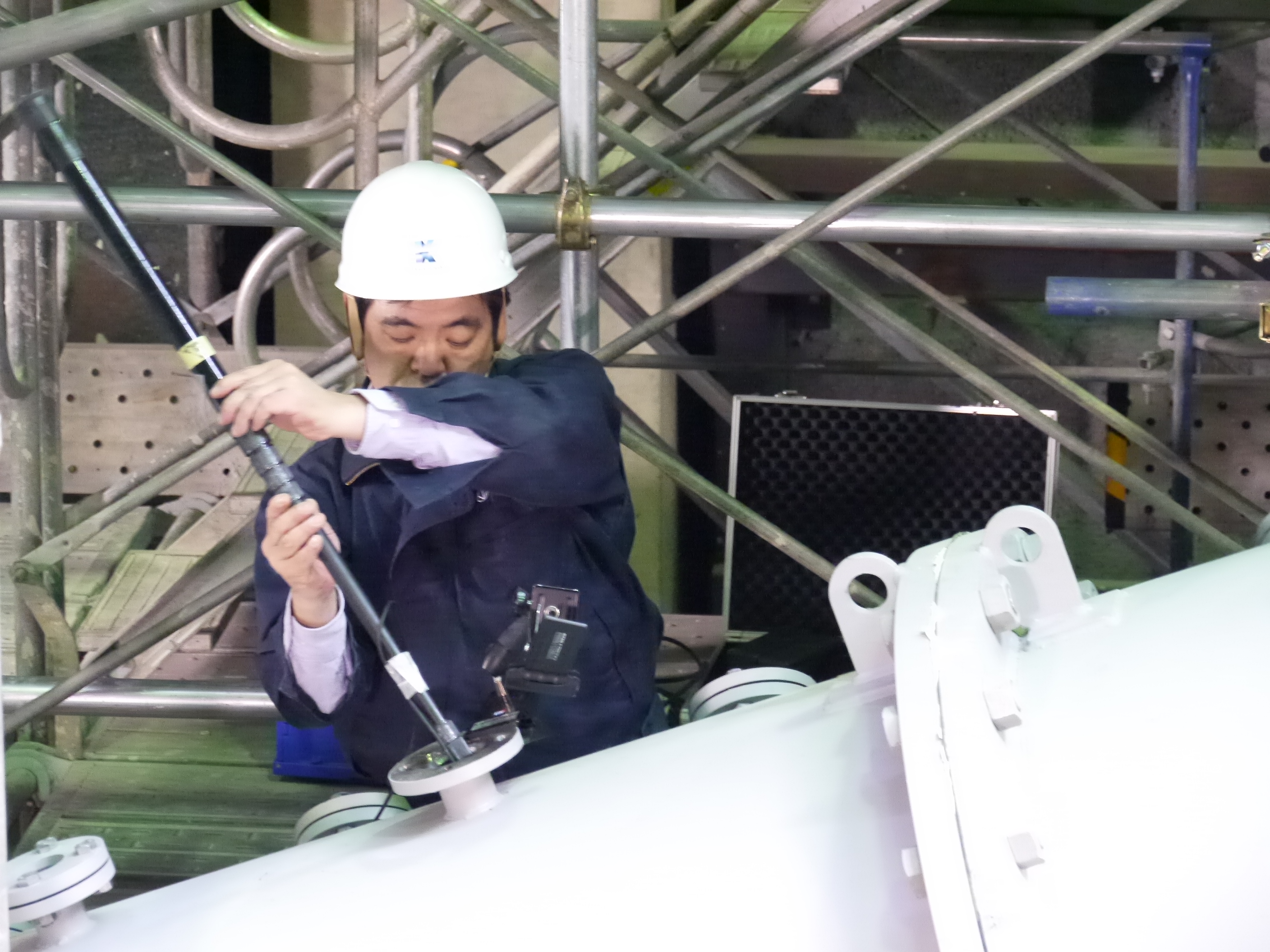
Installation of a camera to the testing device for recording/observing


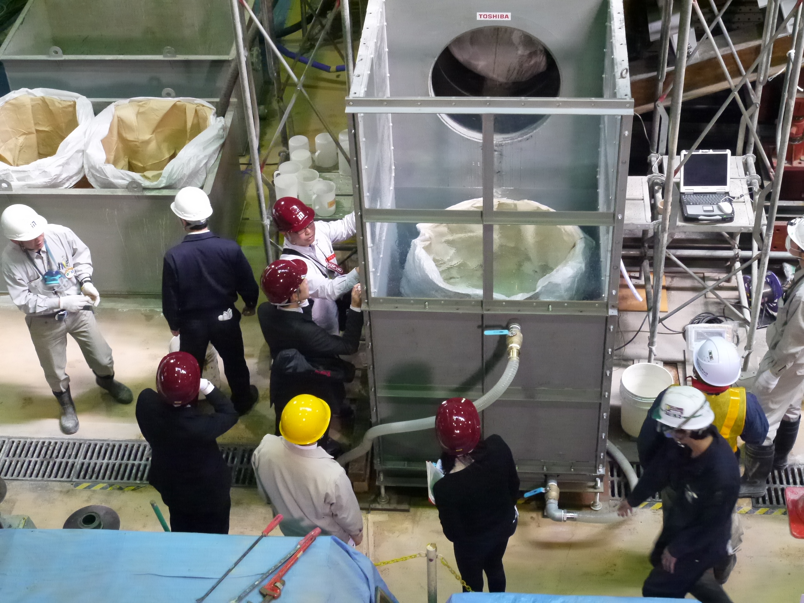
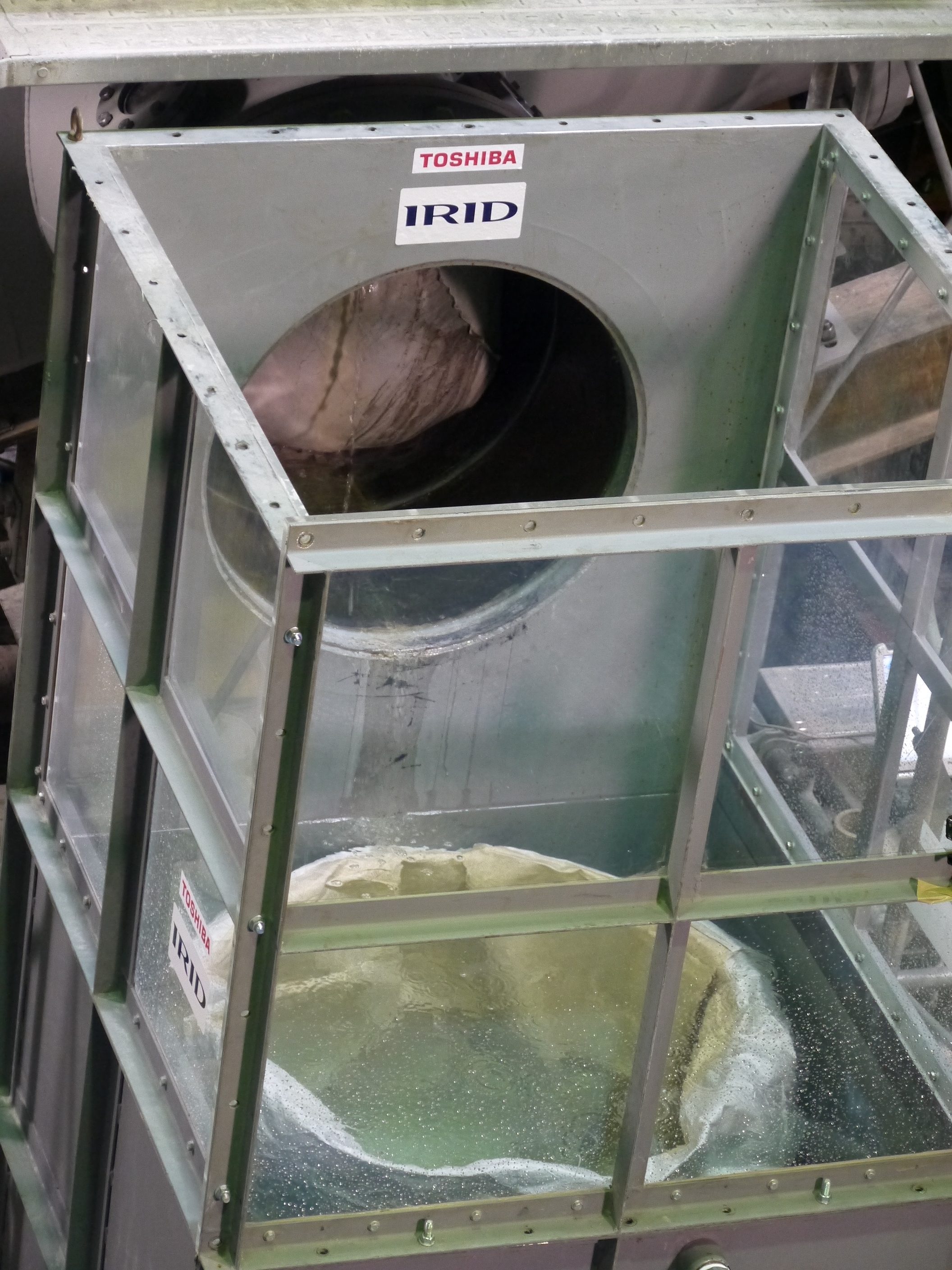
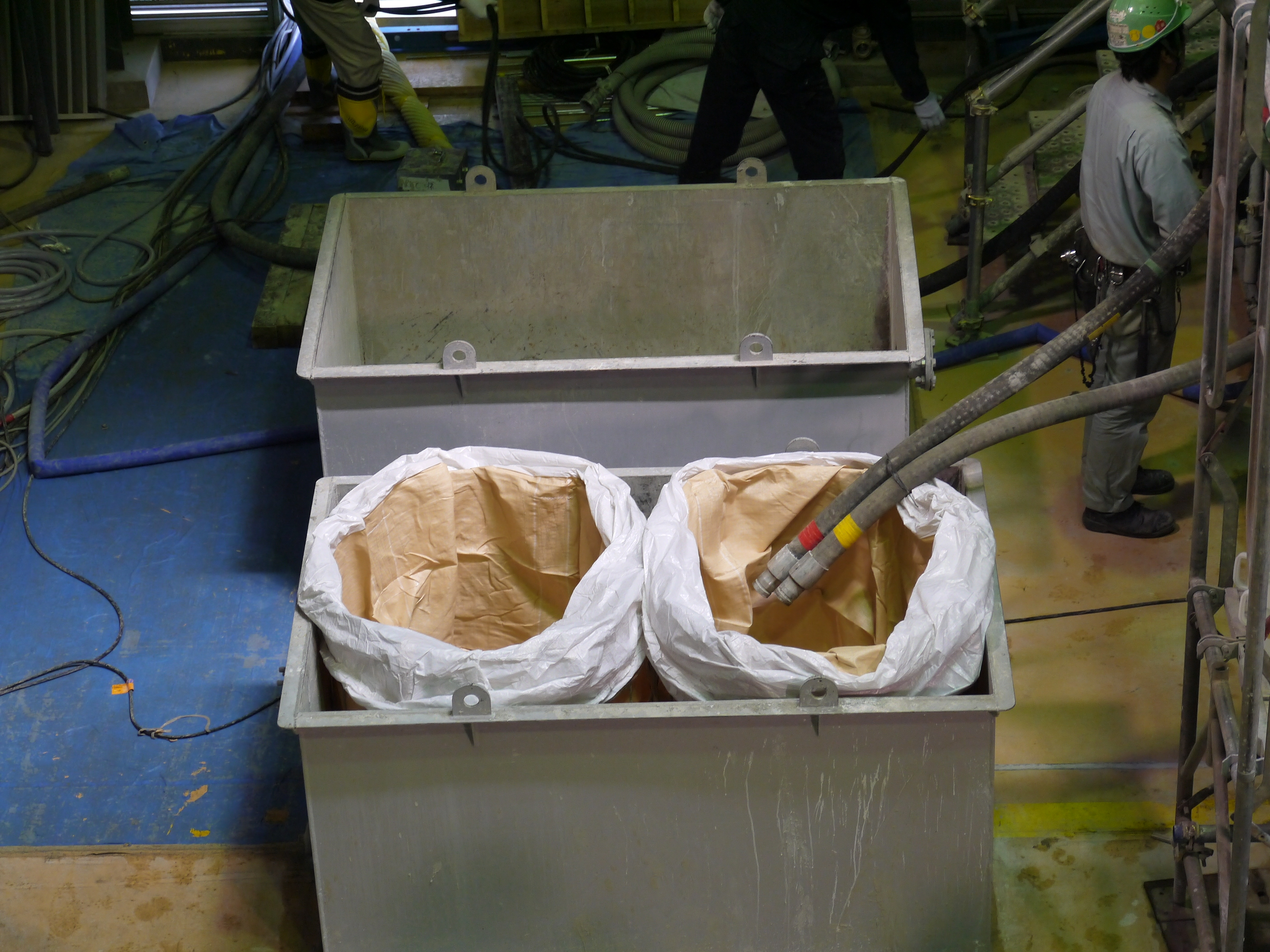
Simulated portion of vent header for testing device (tanks for storage and measurement of water leakage)
Close view of simulated portion of vent header for testing device (tanks for storage and measurement of water leakage)
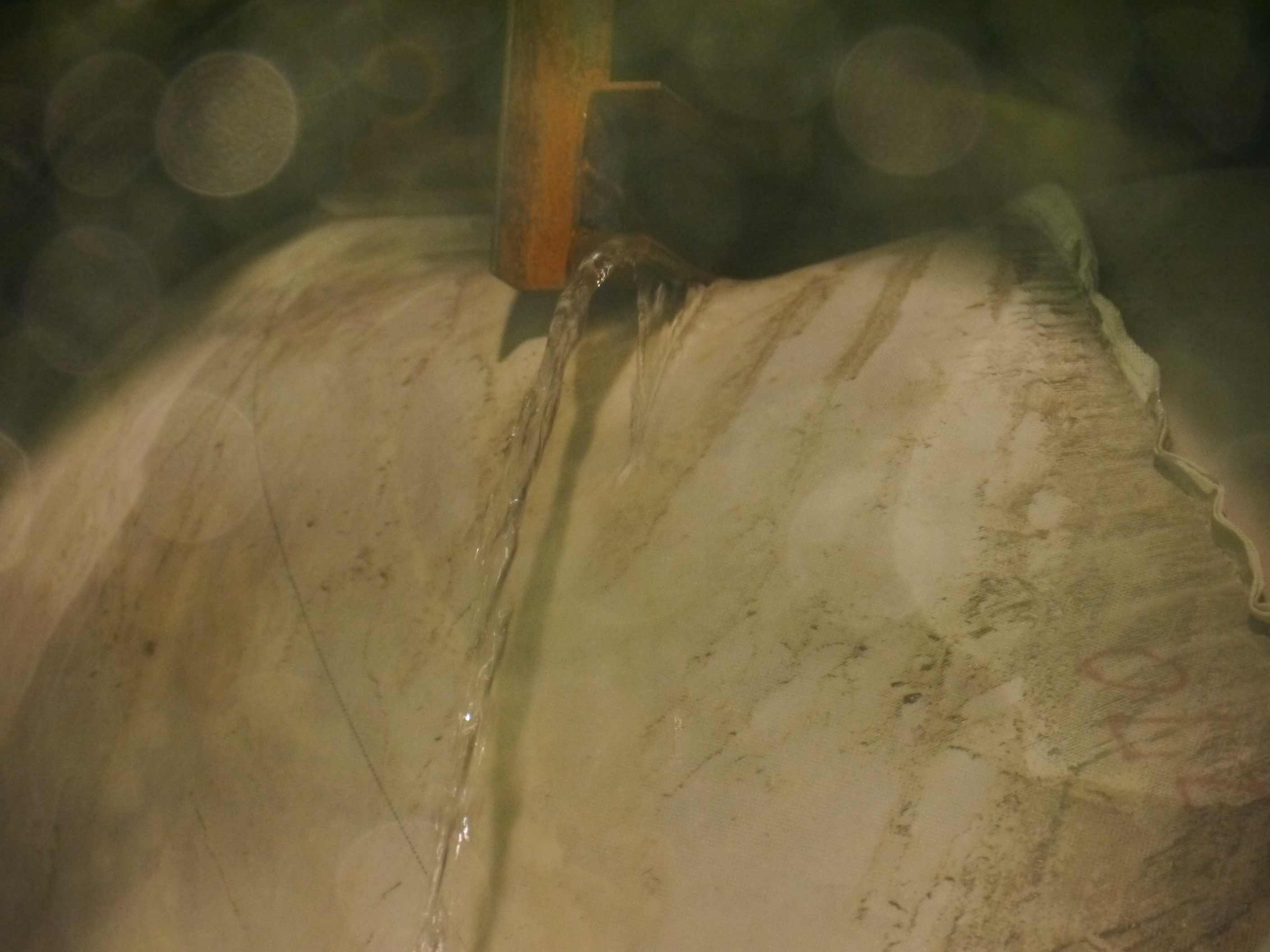
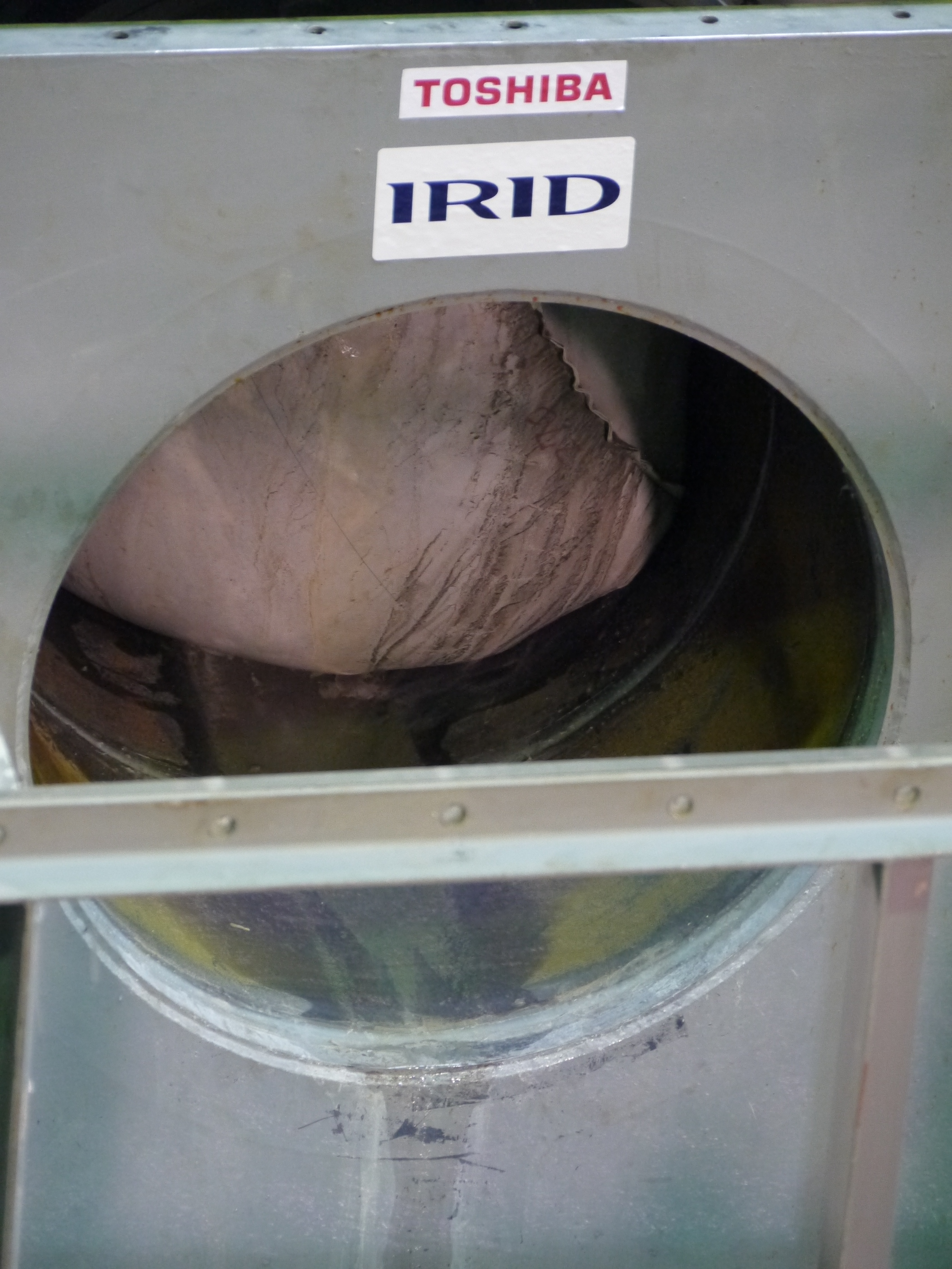
Inflatable bag expanding around the interference, and water leaking from the gap, as viewed from vent header.
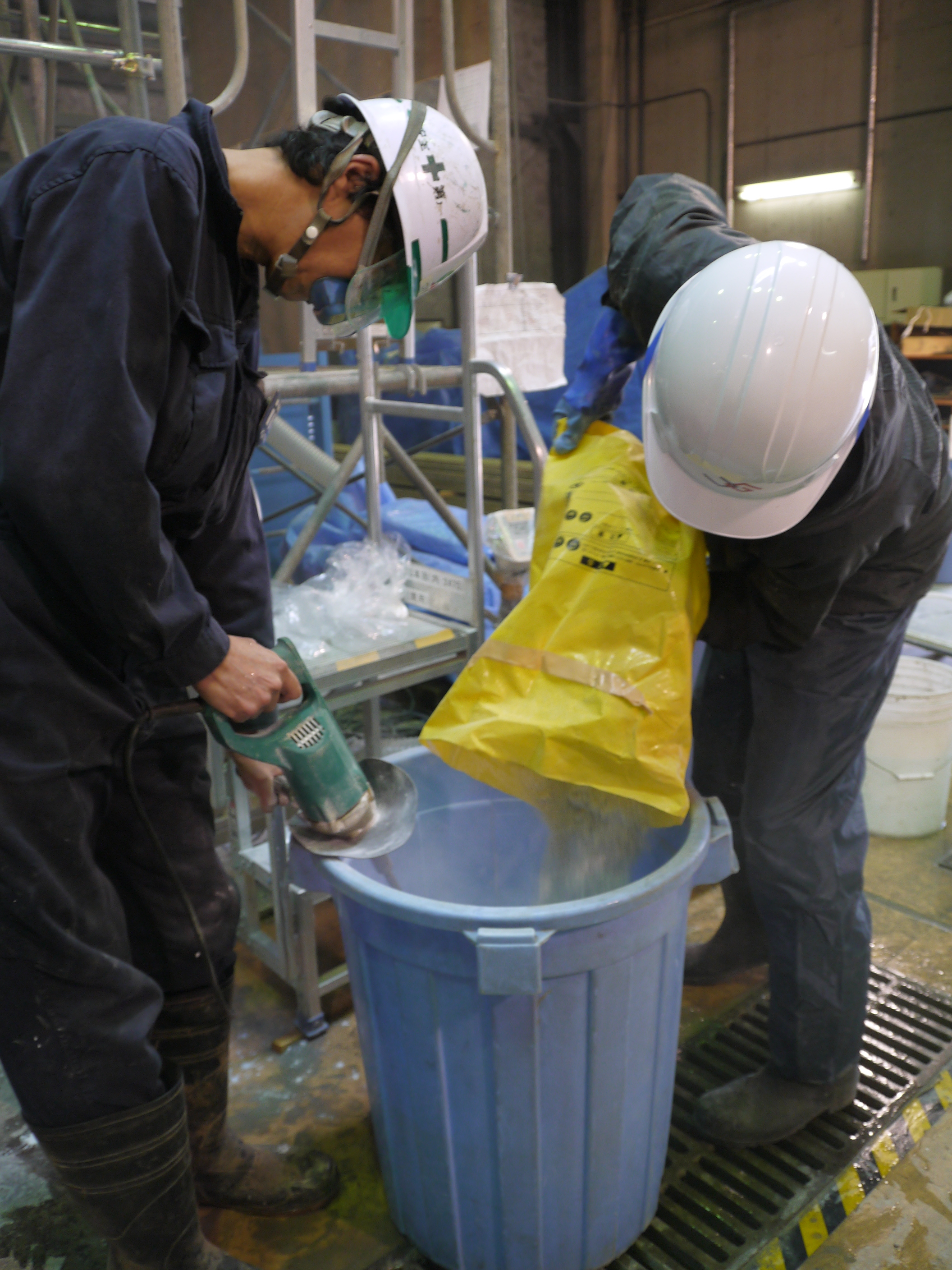
Mixing additive agent to be used in the cement-based material
Simulated portion of vent header for testing device (when water leaks)


Branch pipes to collect sample for quality control test during grouting and material storage facility
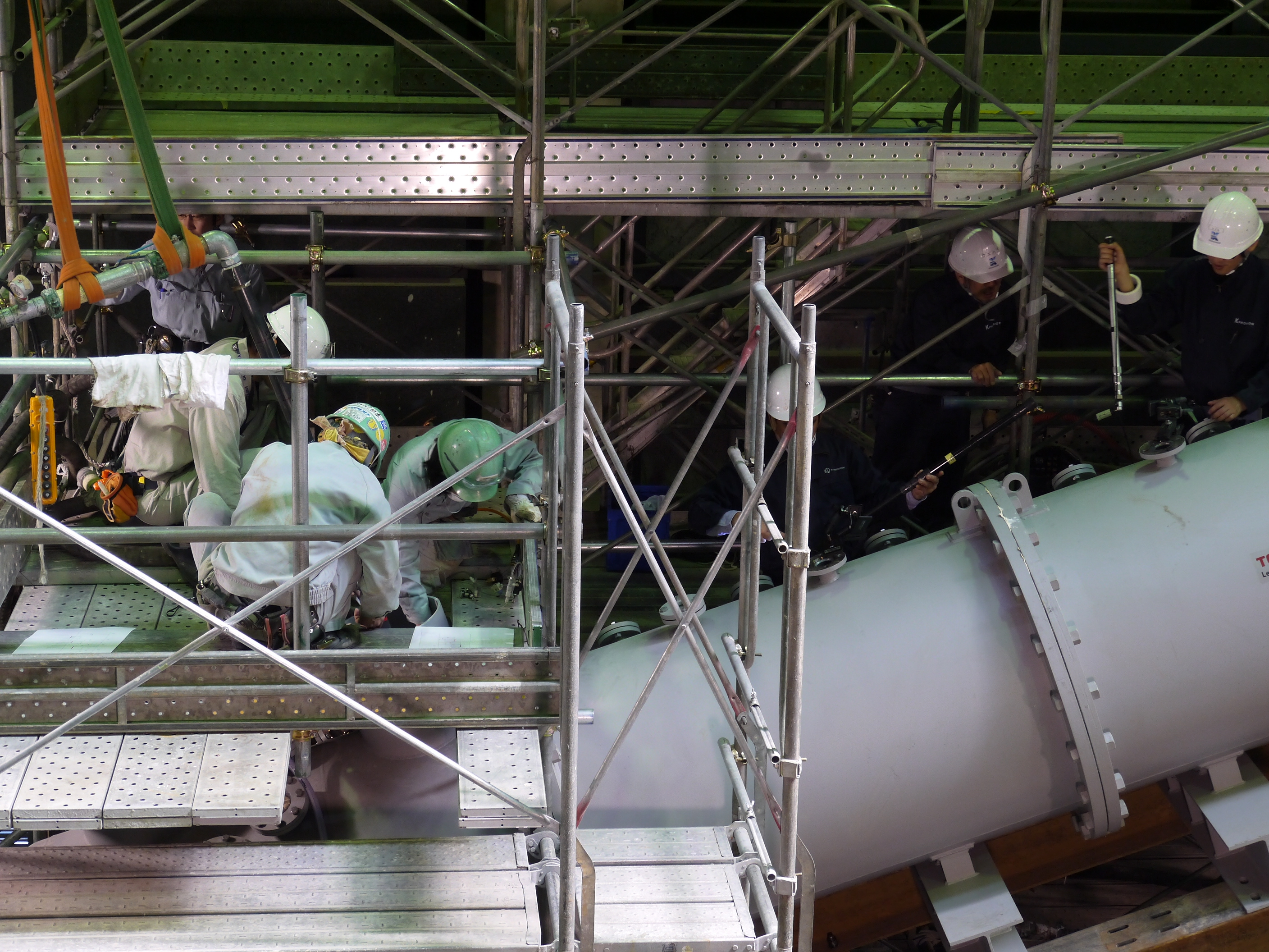
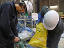
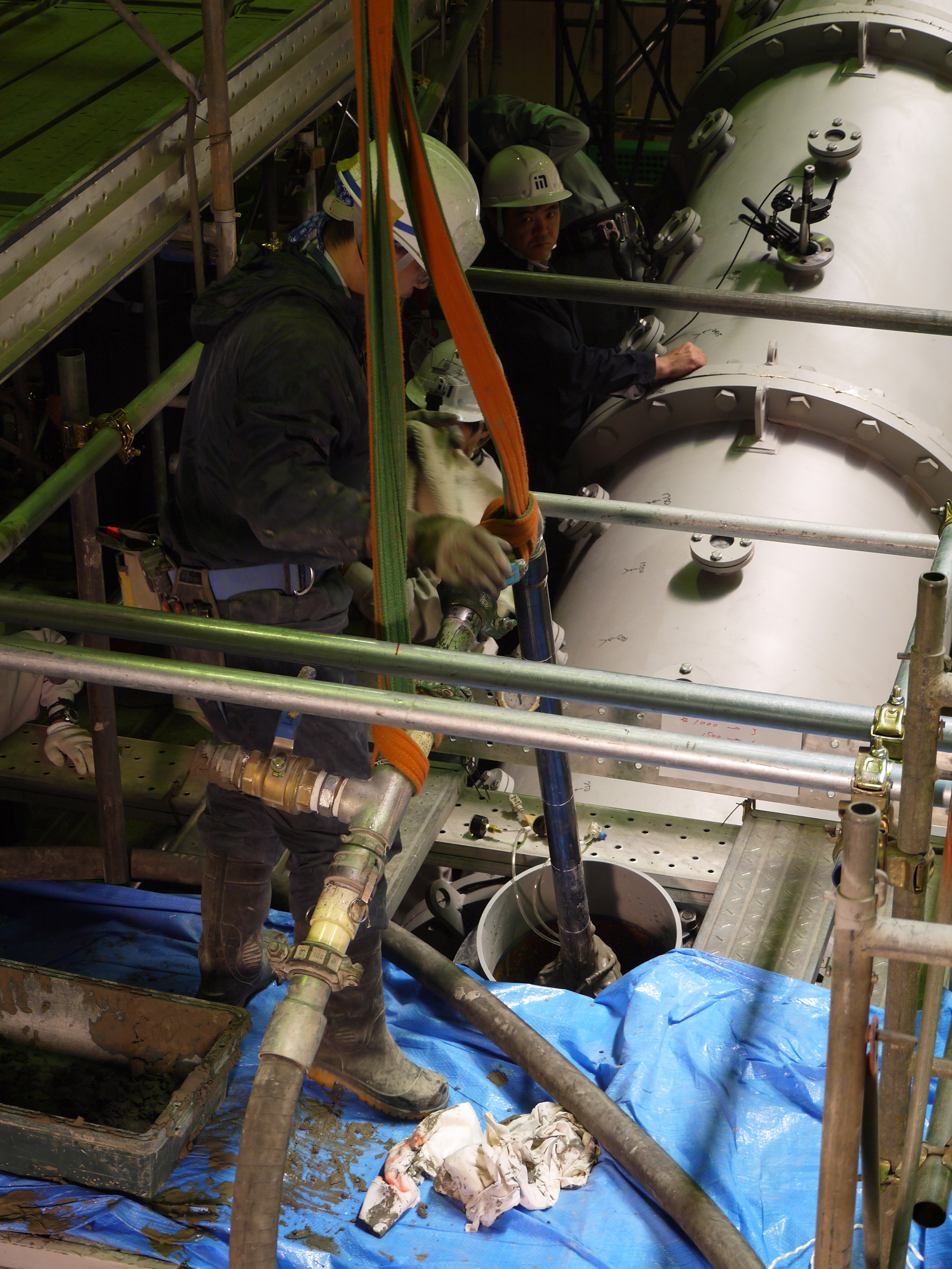
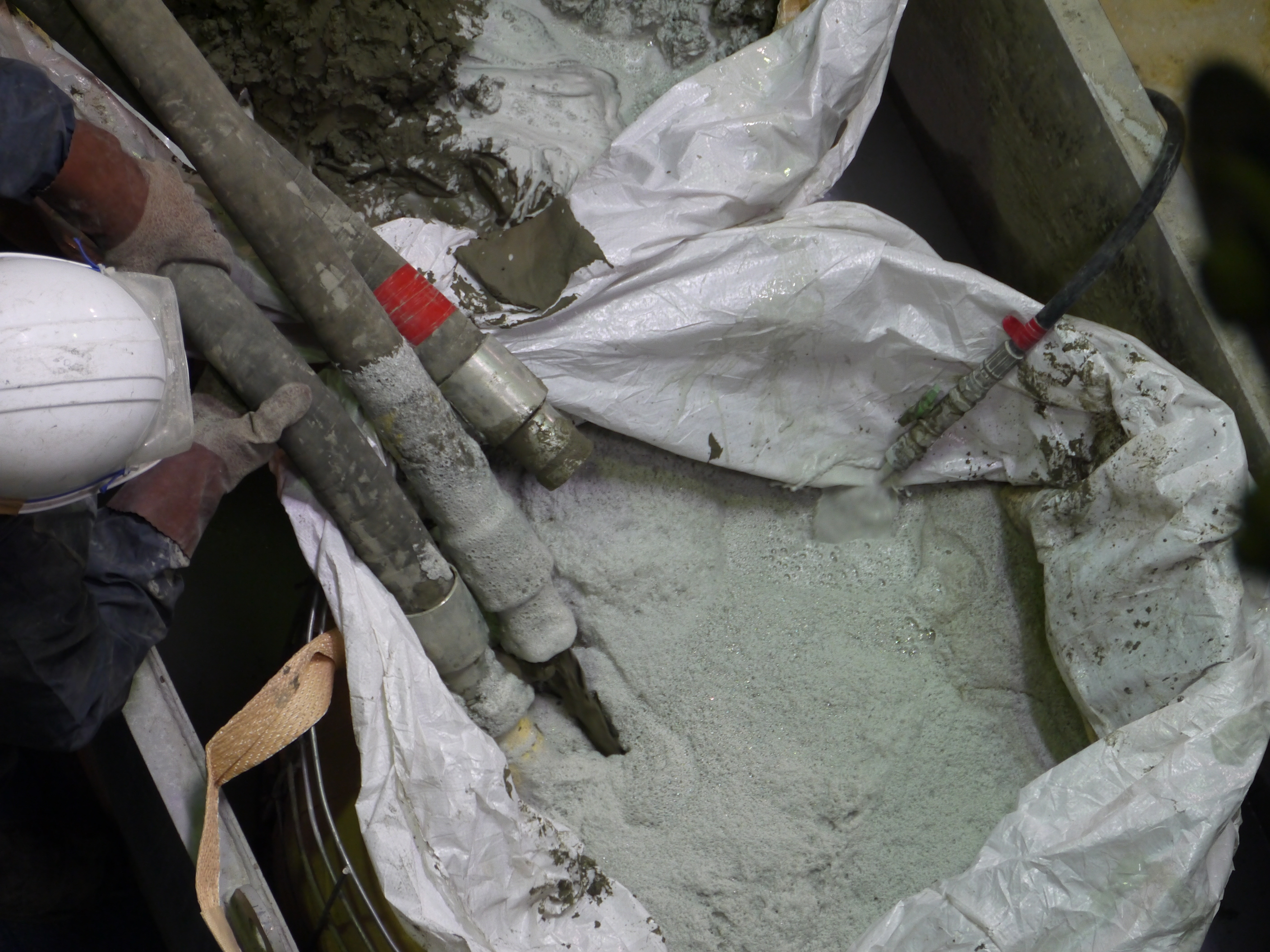
Placement of water stop material
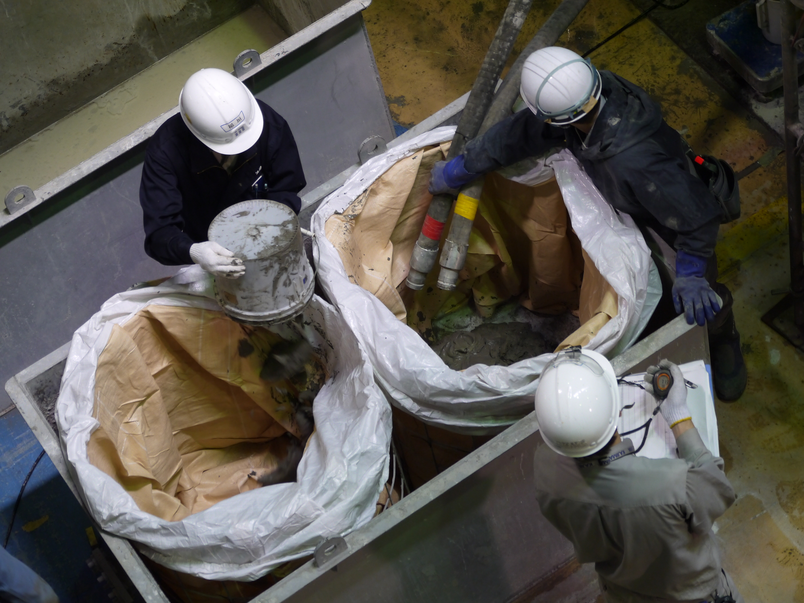
Sampling test for quality control during placement of water stop material
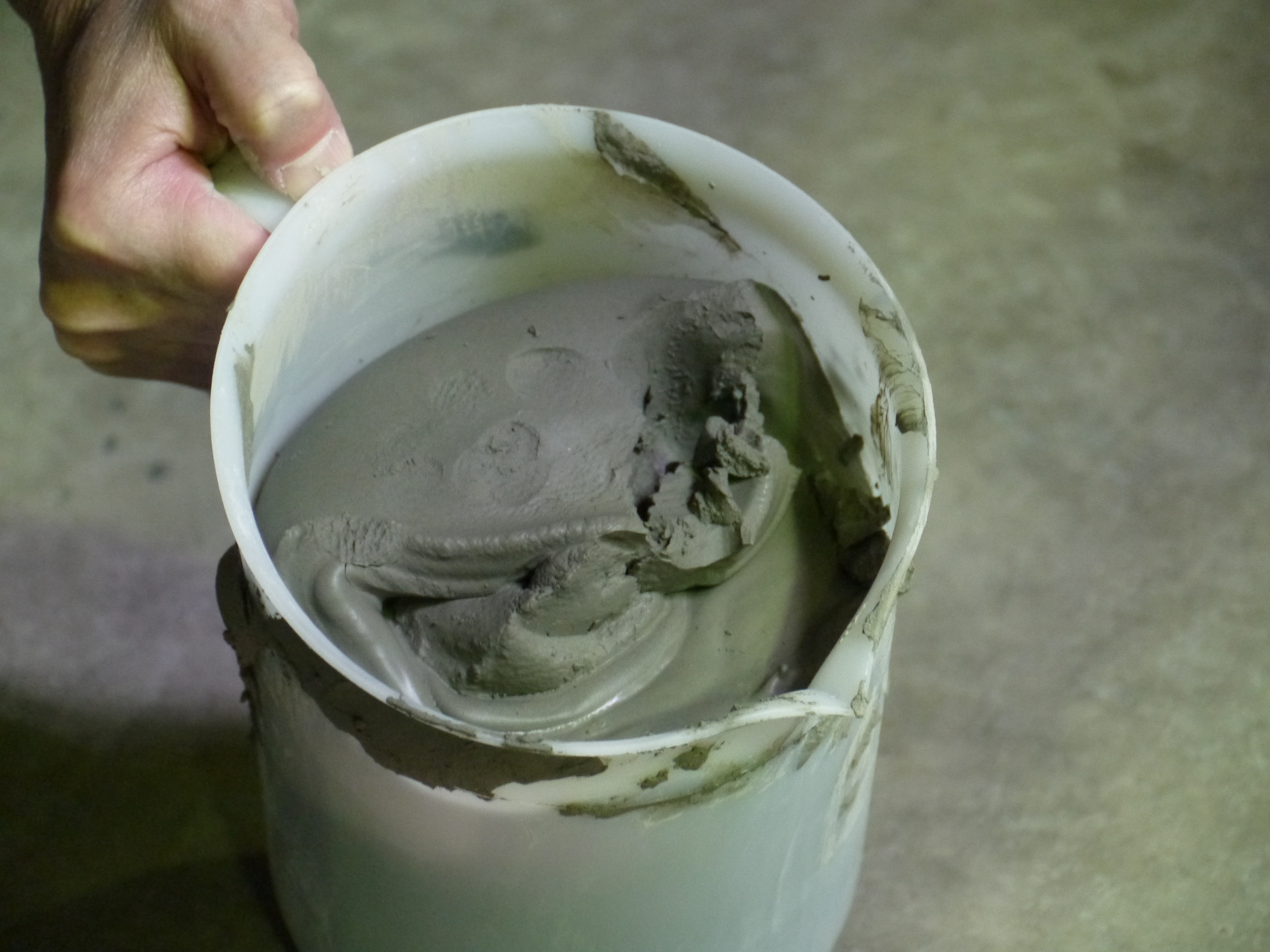
Cement-based water stop material used for the test this time (plastic grout)
Grouting construction (placing by the tremie method)


Checking piling up status of water stop material, as viewed from monitoring window on the testing device.
Simulated portion of vent header for testing device (after placing water stop material)

Cement-based water stop material used for the test (plastic grout)

Checking status of water stop material piled up
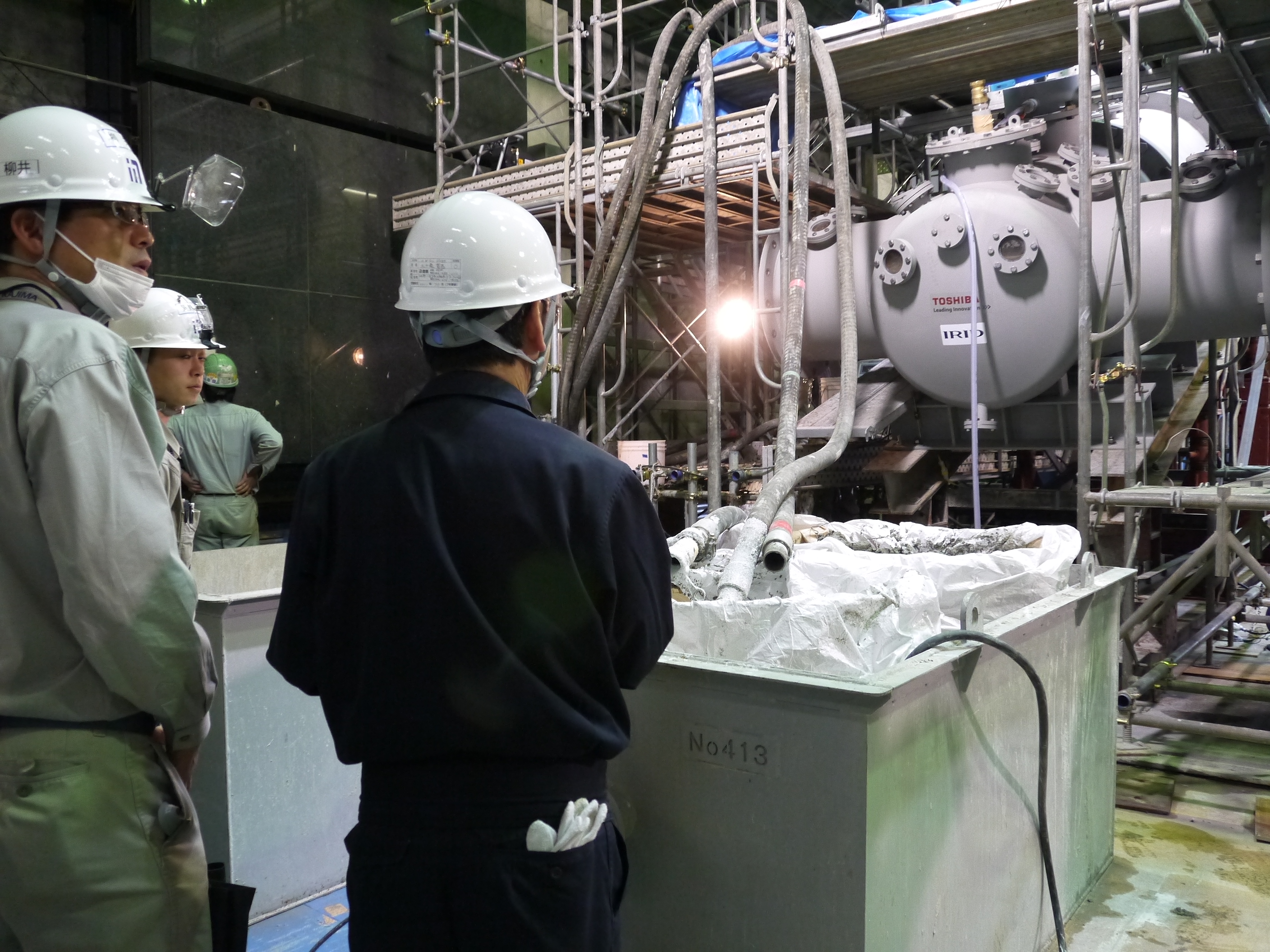
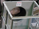
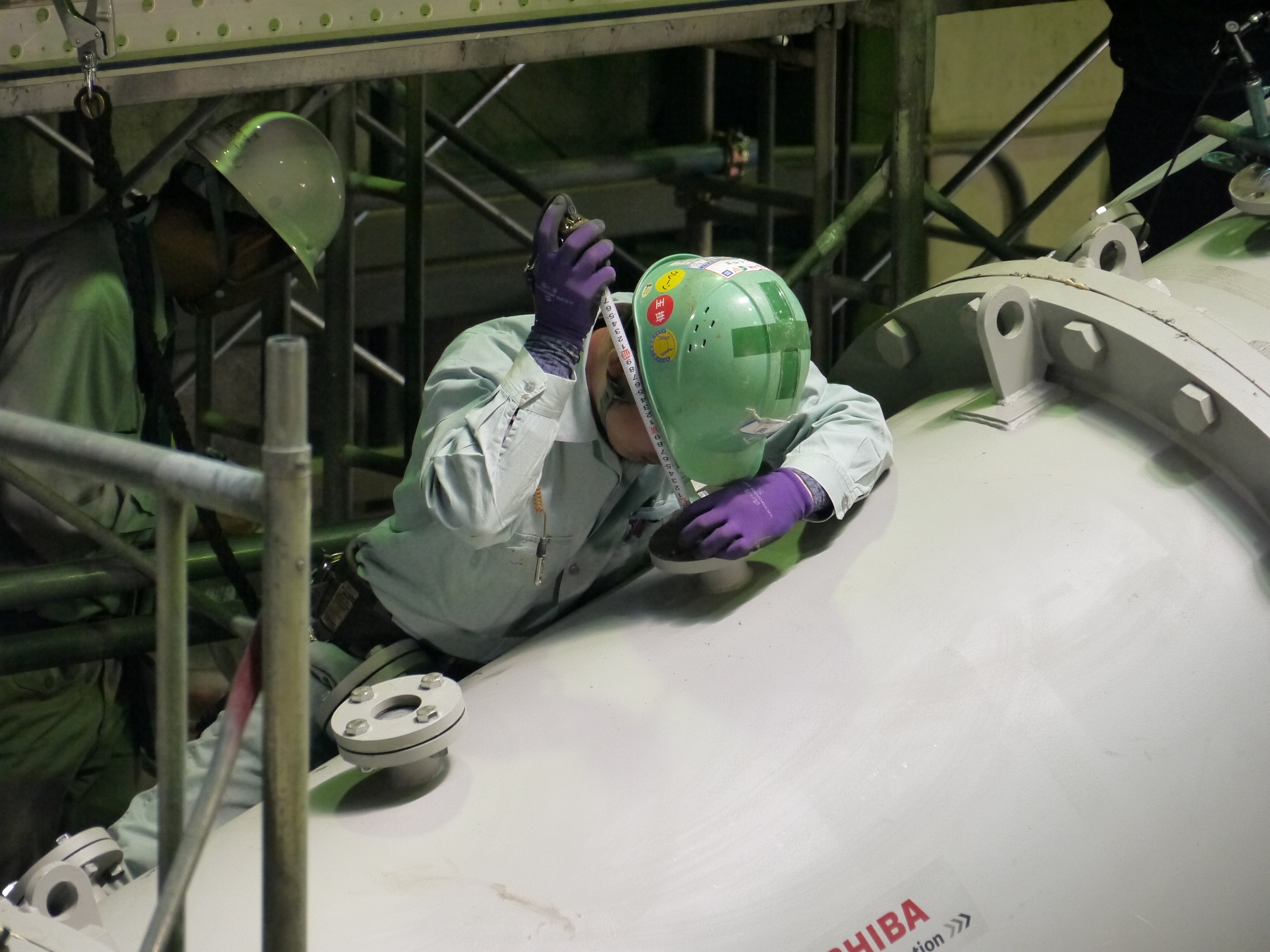
Bottom head of testing device (vent header partially simulated from the both side of vent pipe)

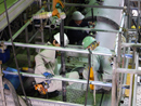
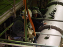
Toshiba staff checking the grouting

- Research and Development
- Released research report
- FY 2017 R&D Report
- Introduction Research
- Survey Device (Shape-changing Robot) Deployed to Inspect Interior of Primary Containment Vessel (PCV)
- Work Training of Device (Shape-changing Robot) to Inspect Interior of Primary Containment Vessel (PCV) [Hitachi-GE Nuclear Energy]
- Development status of equipment for internal PCV investigation [TOSHIBA]
- Robots working inside the buildings at Fukushima Daiichi NPS (Part III) Swimming robot & Crawling robot
- Robots working inside the buildings at Fukushima Daiichi NPS (Part II) MHI-MEISTeR
- Robots working inside the buildings at Fukushima Daiichi NPS Rosemary & Sakura
- Development Status of PCV Leakage Investigation Devices (Toshiba)
- Preliminary Test for “Water Stoppage Method” by Grouting into the Vent Pipe